Geometry Matrix
This article requires a fundamental knowledge about mathematical matrix. If you are not sure, I recommend to read the article Matrix in Ebitengine.
Code
To execute this program, you need the image file gopher.png at the same directory:

The result will be like this:

How the code works
The program is almost same as render-an-image example. The difference is whether DrawImageOptions is specified or not at the DrawImage call. In this example, a GeoM is adjusted. GeoM represents an affine matrix to translate, scale or rotate the image.
In this example, the image is translated by (50, 50) first, and scaled by (1.5, 1). In Ebitengine, Y axis is not upward but downward. Then, tralslating by (50, 50) means that the image is moved by 50 pixels rightward, and by 50 pixels downward. For scaling, the origin point is upper-left and the directions are also downward and rightward.
\begin{aligned} \begin{bmatrix} a & b & t_x \\ c & d & t_y \\ 0 & 0 & 1 \\ \end{bmatrix} \end{aligned}
While GeoM is an matrix for 2D dimension, GeoM's dimension is 3. It is because GeoM is an affine matrix, which can represent not only scaling or rotating, but also translating. While scaling and rotating don't change the origin point (upper-left), translating does, and such change cannot be achieved with a non-affine 2-dimension matrix. The last row is always (0, 0, 1).
The geometry matrix is used to determine how to convert the position in the source image to the position in the destination image. In other words, the geometry matrix represents a converting rule of positions. By adjusting the geometry matrix, we can adjust how to render the source image on the destination image.
\begin{aligned} \begin{bmatrix} 1 & 0 & 0 \\ 0 & 1 & 0 \\ 0 & 0 & 1 \\ \end{bmatrix} \end{aligned}
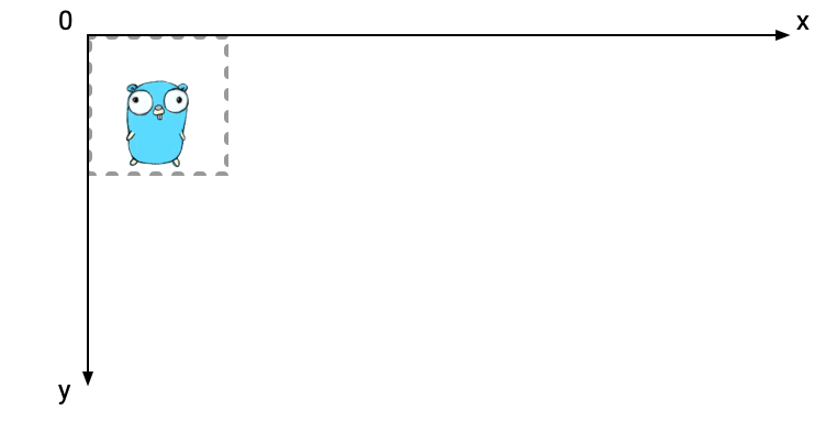
The initial value of GeoM represents an identity matrix. This means that nothing was changed. In Ebitengine, the default location is the upper-left corner.
Note that the direction of the Y axis is downward, not upward. This is different from usual mathematics, but is natural for 2D image rendering.
\begin{aligned} \begin{bmatrix} s_x & 0 & 0 \\ 0 & s_y & 0 \\ 0 & 0 & 1 \\ \end{bmatrix} g \end{aligned}
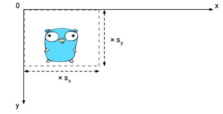
(g *GeoM).Scale left-multiplies a scaling geometry matrix. The origin position is the upper-left corner of the destination image.
If the multiplicand is identity, the image is scaled by the Scale arguments without changing the position of the left-upper corner.
\begin{aligned} \begin{bmatrix} 1 & 0 & t_x \\ 0 & 1 & t_y \\ 0 & 0 & 1 \\ \end{bmatrix} g \end{aligned}
![]()
(g *GeoM).Translate left-multiplies a translating geometry matrix.
If the multiplicand is identity, the image is moved from the left-upper corner by the Translate arguments.
\begin{aligned} \begin{bmatrix} \cos(\theta) & -\sin(\theta) & 0 \\ \sin(\theta) & \cos(\theta) & 0 \\ 0 & 0 & 1 \\ \end{bmatrix} g \end{aligned}
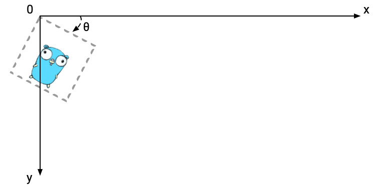
(g *GeoM).Rotate left-multiplies a rotating geometry matrix. The origin position is the upper-left corner of the destination image.
If the multiplicand is identity, the image is rotated by the Rotate arguments. The center of rotating is the left-upper corner.
Of course you can combinate multiple operations of a geometry matrix. They are represented as multiplication of matrices. Note that the order of multiplication matters. For example, the result of translating then scaling an image is, in general, different from scaling then translating the image. In Ebitengine, operations are chained by left-multiplying, then the actual operation order is right to left in mathematical expressions.
\begin{aligned} \begin{bmatrix} 1 & 0 & t_x \\ 0 & 1 & t_y \\ 0 & 0 & 1 \\ \end{bmatrix} \begin{bmatrix} s_x & 0 & 0 \\ 0 & s_y & 0 \\ 0 & 0 & 1 \\ \end{bmatrix} \end{aligned}
![]()
\begin{aligned} \begin{bmatrix} s_x & 0 & 0 \\ 0 & s_y & 0 \\ 0 & 0 & 1 \\ \end{bmatrix} \begin{bmatrix} 1 & 0 & t_x \\ 0 & 1 & t_y \\ 0 & 0 & 1 \\ \end{bmatrix} \end{aligned}
![]()